
 Home
Home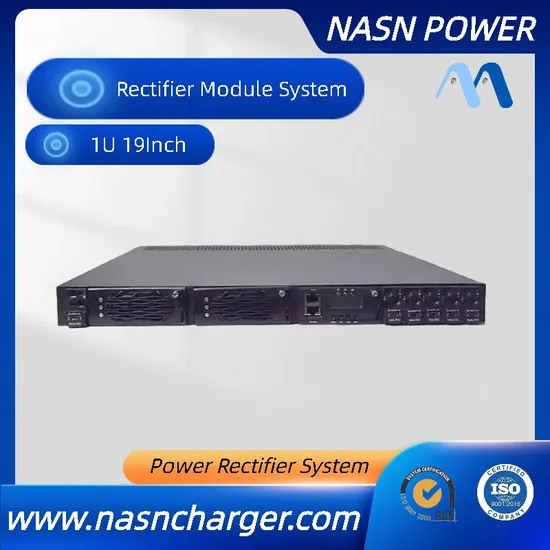
19inch 1u Embedded 48V Rectifier DC Power Supply System
Basic Info.
| Model NO. | Rectifier |
| Output Power | 401 - 500W |
| Input Voltage | 110-220V |
| Connection Mode | Series Switching Power Supply |
| Starting Mode | Self-excited Switching Power Supply |
| Voltage Regulating Mode | Frequency Modulation Type |
| Power Supplying System | Terminal Power Distribution Equipment |
| Energy Transmission | One-way Transmission |
| Modulation System | PWM |
| Certification | CE |
| Input | 3phase 380V Single Phase 220V |
| Output | 24V/48V |
| Output Current | 24V70A/ 48V50A |
| Protection | High Tempeturer Protection |
| Factory | Factory Supply |
| Used for | 48V Battery or 48V Load |
| LCD Screen | Yes |
| Support | OEM/ODM |
| Package | Carton Box |
| Communication | 485 232 Snmp |
| Model | Nasn Rectifiers |
| Name | Switch Mode Power Supply |
| Application | AC /DC Distribution System |
| Power Supply | Hot Swappable and Plug and Play |
| N+1 Redundancy | Embedded Modular System |
| Transport Package | Carton |
| Specification | 540*44*13mm |
| Trademark | NASN |
| Origin | China |
| HS Code | 8504409992 |
| Production Capacity | 100/Month |
Packaging & Delivery
Package Size54.00cm * 44.00cm * 13.00cm Package Gross Weight9.000kgProduct Description
NASN rectifiersNASN rectifiers bring advanced technology to the DC power industry. Innovative engineering combines the best in efficiency and reliability to meet the power requirements for a variety of system applications. This rectifier is specifically designed to recharge all types of stationary batteries for large utility, petrochemical and industrial uses. The fan cooled rectifier module has extremely high density providing the most power in the least amount of space. A compact shelf accommodates four rectifiers per 19in 1U shelf and can be paralleled up to 5*1U 19in shelf. Local and remote setup, adjustment and control is a simple, single-step process with the rectifier System Controller. By utilizing TCP/IP technology, complete configuration and monitoring of power equipment is possible through a Windows Internet Explorer browser. We can provide turnkey solutions for outside plant, headend, telecommunications, industrial and renewable energy applications. We work to combine your small-, medium- and large-scale projects with the necessary installation resources.
Telecom Rectifier 220 V AC to 220 VDC 10A Telecom Power Supply
AC DC Rectifier with 24V 48V 110V 220V Module for Telecom
FAQQ1: What kind of EV Charger do you have?AC and DC charger with connectors Type2, CCS1/CCS2, CHAdeMO, GB/T, etc.
Q2: Do you provide customized product?
We provide OEM and ODM services for clients.
Q3: What is the delivery time of EV charger?
About 4-6 weeks.
Q4: What about your warranty of EV Charger?
Generally 2 years. Our warranty period depends on customer's requirements and we always put customer's need as priority.
Q5:How do you package it ?
A:We pack in cartons.
Q6:what's the MOQ?
A:For LOGO, color or other special requirements, a minimum of 20 is required. If you do not have these requirements you can buy
directly, we will ship within 3-10 days.
Q7:Can you produce according to the samples?
A:Yes, we can produce by your samples or technical drawings. We can build the molds and fixtures.
Q8:Do you test all your goods before delivery?
A:Yes, we have 100% test before delivery.
Q9:What is your terms of delivery?
A:EXW, FOB, CFR, CIF, DDU.
Q10:What is your terms of payment?
A:We accept all methods of payment: paypal, T/T, credit card, West Union... Please contact us for more details.
| Input Voltage Range | 85Vac to 300Vac |
| Rated Input Voltage | 110Vac / 220Vac |
| Nominal Input Voltage Range | 200Vac to 250Vac |
| Frequency Range | 45Hz-66Hz |
| Maximum Input Current | 18A |
| Surge Current | Standard: EN/IEC61000-4-5 |
| Efficiency | ≥96%@230Vac peak efficiency |
| Power Factor | ≥0.99@220Vac/20%~100% Load |
| Input Current Thd | <5%@ 50% Load <8%@ 20% Load |
| Leakage Current | <3.5mA@264Vac |
| Rated Power | 3000W(176Vac~290Vac) 1250W(85Vac~175Vac linear derating) |
| Maximum Input Rush Current | 30A |
| Input Fuse | with 25A fuse on L&N |
| Maximum Input Voltage | 320Vac(power good) |
| Input Voltage Range | 120Vdc to 400Vdc |
| Rated Input Voltage | 340Vdc |
| Nominal Input Voltage Range | 200Vdc to 400Vdc |
| Maximum Input Current | 17A |
| Surge Current | Standard: EN/IEC61000-4-5 |
| Reverse Polarity Protected | No damage even with the wrong polarity |
| Input Fuse | Fuse on both the positive and negative polarities. |
| Efficiency | ≥96%@325Vdc peak efficiency |
| Rated Power | 3000W(200Vdc~400Vdc) 1800W(120Vdc~200Vdc linear derating) |
| Maximum Input Voltage | 450Vdc(power good) |
| Output Voltage | +53.5Vdc |
| Output Voltage Setting Value | +53.5±0.1Vdc |
| Adjustable Output Voltage Range | +42Vdc~+58Vdc |
| Current-Unbalance | ≤±3% |
| Source Effect | ±0.1% |
| Load Effect | ±0.5% |
| Stabilized Voltage Precision | ±0.6% |
| Minimum Current | 0A |
| Rated Current | 50A |
| Peak Current | [email protected]V |
| Temperature Coefficient(1/°C) | ≤±0.02% |
| Power Failure Hold-Up Time | 10ms |
| Stand-By Power Consumption | ≤4W |
| Maximum Capacitive Load | 4000uF |
| The Maximum Number Of Modules In Parallel Connection | 31 |
| Performance Index | Maximum | Remark |
| Ripple & noise(peak-to-peak) | 200mVp-p | bandwidth≤20M |
| Voltage Overshoot | Jump Slope | Load Fluctuation | Recovery Time | Output Overshoot |
| +53.5V | 0.1A/uS | 25%~50% load, 50%~25% load, 50%~75% load, 75%~50% load | ≤200us | ≤±5% |
| +58V | 0.1A/uS | 0%~100% load, 100%~0% load | over-temperature protection untriggered |
| Output Voltage | Load Fluctuation | Output Overshoot |
| +53.5V | Startup overshoot | <1% |
| Item | 220Vac@25ºC |
| Startup Delay | 3S~8S |
| Input Voltage | Maximum Output Power |
| 176Vac~290Vac | 3000W |
| 85 Vac~176Vac | linear derating |
| 85Vac | 1250W |
| Input Voltage | Maximum Output Power |
| 200Vdc~400Vdc | 3000W |
| 120 Vdc~200Vdc | linear derating |
| 120Vdc | 1800W |
| Environmental Temperature | Maximum Output Power |
| -40~55ºC | 3000W |
| 55~65ºC | linear derating |
| 65ºC | 2400W |
| 65~75ºC | linear derating |
| 75ºC | 1200W |
| Noise Voltage | Maximum | Remark |
| telephone weighted noise voltage | ≤2mV | |
| wide band noise voltage | ≤50mV | 3.4~150KHz |
| ≤20mV | 150~30000KHz | |
| discrete noise voltage | ≤5mV | 3.4~150KHz |
| ≤3mV | 150~200KHz | |
| ≤2mV | 200~500KHz | |
| ≤1mV | 500~30000KHz |
| Output Voltage | Remark |
| +53.5V | long - term short circuit is allowed, automatic recovery is triggered when short circuit fault disappears |
| Input Voltage | Remark |
| 290~300Vac | The alarm light is on with normal output |
| 310±5Vac | Output is off and the input is disconnected from the power grid. Output can be recovered automatically when the voltage is normal. |
| input recovery point hysteresis>10V |
| Input Voltage | Remark |
| 390~400V dc | The alarm light is on with normal output |
| 420±5V dc | Output is off and the input is disconnected from the power grid. Output can be recovered automatically when the voltage is normal. |
| input recovery point hysteresis>10V |
| Input Voltage | Remark |
| 80±5Vac | Output is off and can be recovered automatically when the voltage is normal |
| input recovery point hysteresis>5V |
| Input Voltage | Remark |
| 110±5Vdc | Output is off and can be recovered automatically when the voltage is normal |
| input recovery point hysteresis>5V |
| Temperature | Remark |
| ≤55ºC | The module runs properly with the maximum output power and without temperature protection |
| 55ºC~65ºC | linear derating of module power to 2400W |
| 65ºC~75ºC | linear derating of module power to 1200W |
| >75ºC | The module recovers automatically with the temperature hystersis>10ºC in the state of shutdown when the temperature is above 75ºC |
| Indicator | Color of Indicator | Normal State | Abnormal State | Root Reason |
| running indicator | Green | On | Off | Mains power failure (no AC input, AC input over-voltage/under-voltage), no output of the module. |
| protection indicator | Yellow | Off | On | Temperature Pre-alarm (ambient temperature over 65°C ~ thermal shutdown) Dormancy shutdown (when dormancy shutdown, only the protection indicator light is on without any alarm). Communication interruption (protection indicator flickers) |
| malfunction lndicator | Red | Off | On | Output over-voltage shutdown, fan failure, over-temperature shutdown, no output caused by the module internally. |
DC Output Characteristics
The module shall be capable of operating in "Auto Float cum-Boost charger" mode. It shall be programmed to operate as a float rectifier or a Boost charger depending on the condition of the battery
Auto Float Mode
Float voltage of each rectifier module shall be set as given below: Normal Float & Boost voltage for VRLA battery is 2.25V and 2.3V/Cell respectively. For conventional battery it shall be 2.15V and 2.42V/cell, respectively. For 110V/20Amp charger 55cells of 2V each will be used and for 48V/25A charger 24 cells of 2V each will be used. The module should have a range from 2.0 - 2.3V/cell in float mode & 2.2 - 2.5V/cell in boost mode to meet the requirement of VRLA as well as conventional batteries. The DC output voltage shall be maintained within ± 1% of the half load pre-set voltage in the range 25% load to full load when measured at the output terminals over the full specified input range.
Auto Boost Charge Mode
In auto boost charge mode, CONVERTER shall supply battery and equipment current till terminal voltage reaches 2.3V (VRLA battery) /2.42V (Low Maintenance battery) per cell.and shall change over to Auto Float mode after a defined delay of 0, 1, 2, 4 hours adjustable, to be set as per battery manufacturer's specification.
Efficiency The efficiency and Power factor of the CONVERTER in auto float and auto boost mode shall be as follows: Nominal input - 150-275V Output - Full Load, Efficiency > 90% and Power factor >0.95 to unity And for Nominal input - 150-275V Output - 25% to 100%, Efficiency > 85% and Power factor >0.9 Note: Active power factor correction circuit shall be adopted.
Total Harmonic Distortion The total line harmonic voltage distortion shall not be more than 10%. The total current harmonic distortion contributed by CONVERTER at the input shall not exceed 10% for all input condition and load 50% to 100% of the rated capacity.
Soft Start Feature
Slow start circuitry shall be employed such that CONVERTER module output voltage shall reach
its nominal value slowly within 10 to 20 seconds, eliminating all starting surges.
The maximum instantaneous current during start up shall not exceed the peak value of the
rectifier-input current at full load at the lowest input voltage specified.
Voltage Overshoot/Undershoot (with battery disconnected)
The CONVERTER modules shall be designed to minimize output voltage overshoot /
undershoot such that when they are switched ON, the DC output voltage shall be limited to ± 5%
of the set voltage and return to its steady state within 20 millisecond for any load of 25% to
100%.
The DC output voltage overshoot for a step change in AC mains from 150V to 275V shall not
cause shut down of CONVERTER module and the voltage overshoot shall be limited to ±5% of
its set voltage and return to steady state within 20ms.
The modules shall be designed such that a step load change of 25% to 100% or vice- versa
shall not result in DC output voltage overshoot/undershoot of not more than ±5% of the set value
and return to steady state value within 10 millisecond without resulting the unit to trip.
Parallel Operation
The CONVERTER modules shall be suitable for operating in parallel on active load sharing
basis with one or more modules of same type, make and rating.
The current sharing shall be within ± 10% of the individual capacity of each CONVERTER in the
system when loaded between 50 to 100% of its rated capacity.
Alarms & Indication of CONVERTER The following indications, controls & measuring points shall be provided on the front panel of CONVERTER
a) CONVERTER on Auto Float mode FLOAT Green b) CONVERTER on Boost Charge mode BOOST Green c) Mains available MAINS Amber
Alarm Indication with LED: a) Rectifier module over voltage OVER VOLTAGE Red b) Rectifier module under-voltage UNDER VOLTAGE Red c) DC output fail OUTPUT FAIL Red d) CONVERTER Overload/ short circuit OVERLOAD/ SHORT CIRCUIT Red e) Fan fail FAN FAIL Red Note: "Provision shall be made for stopping the audio alarm with a non-locking push button. a) Float voltage adjustment (float) b) Boost voltage adjustment (boost) c) Overload current setting (OL) d) Voltage monitoring point suitable for measurement by standard multimeter.
Snmp Electric Power Supply 220VAC to 48VDC 50A Rectifier Power for Telecom